

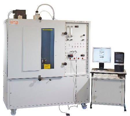
The Federal Aviation Administration (FAA) regulates aircraft operating in the US but its guidelines are followed worldwide. Fire tests for materials used in passenger aircraft are detailed in the FAA Aircraft Materials Fire Test Handbook. We provides the following fire testing equipment which are all described in the FAA Fire Test Handbook and are used for regulation:
i) Rate of Heat Release (ASTM E906) OSU Calorimeter – used to expose aircraft interior cabin materials to an incident radiant heat flux of 35kW/m2. This will determine if the
material complies with FAR 25.853 [a-1] requirements.
ii) NBS Smoke Density Chamber (BS 6401, ASTM E662, ISO 5659, NES 711) – for the determination of smoke generated by solid materials and assemblies mounted in the vertical orientation within a closed chamber.
iii) Thermal/Acoustic Insulation Flame Propagation Apparatus (FAR Part 25 Appendix F Part VI, Airbus AITM 2.0053, Boeing BSS 7365) – evaluate the flammability and flame
propagation characteristics of thermal/acoustic insulation when exposed to both a radiant heat source and flame in a test chamber
iv) FAR Bunsen Burner Test Apparatus – conforms to the fire test methods described in FAA Aircraft Material Fire Test Handbook for aircraft materials.

Rate of Heat Release Calorimeter
NBS Smoke Density Chamber

Thermal/Acoustic Insulation Flame Propagation Apparatus

FAR Bunsen Burner Test Apparatus
As the use of adhesively bonded joints and fittings has increased across many industries, the need for testing bond integrity has grown. Metal to metal bonded joints, sandwich constructions with various skin and core materials, bonded carbon fibre composite structures have all become important in manufacturing as well as in-service repair patches and adhesively bonded re-inforcements. The integrity of these bonds is critical to the quality of the final product. Conventional ultrasonic methods can be limited for these applications and so a variety of alternative methods have been developed to handle this range of material combination.
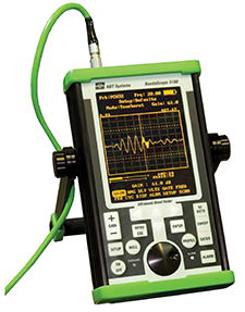
Bondascope Tester
Inspection Methods
- Pitch-Catch RF
- Pitch-Catch Pulsed
- Pitch-Catch Swept
- MIA Fixed Frequency
- MIA Swept Frequency
- Resonance
Application
- Multi-layered laminates
- Skin to core flaws
- Glass fiber/ carbon fiber composites
- Far-side defects
- Honeycomb and foam cores
- Impact damage
- Metal to metal bonding
- Adhesively bonded fittings
- Liquid Ingress
Additive manufacturing (AM) is a process of joining materials to make objects from 3D model data, usually layer upon layer, as opposed to subtractive manufacturing methodologies. Manufacturing components layer by layer with additive processes allows engineers to tailor form, weight, strength, stiffness and other properties to specific use cases.
Additive Manufacturing is driving a revolution in design and manufacturing. The technology lets us directly create parts from a solid drawing, using a wide and growing range of Additive Manufacturing methods. In the best cases, properties can compare favourably to conventional manufacturing processes. The various techniques are applicable to metals, polymers, and even composites and ceramics. Manufacturing components layer by layer to form the parts that have tight tolerances or are load-bearing may need some finish machining steps or heat treatment, but in some cases the parts can be used right out of the additive manufacturing system.
Testing witness coupons is particularly valuable as part of an additive production process. A small testing coupon is produced before and after a complicated build to make sure the system is performing generally as expected. There are several important elements. First, it may be challenging to get standard specimens machined out of additively manufactured components, so you might need to use subscale specimens or a different type of test.

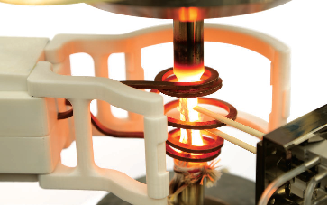
Characterization of 3D-printed components
Manufacturers of aircraft and space vehicles are focused on improving the fuel efficiency of turbine-powered jet engines. Increasing the efficiency of its fleet by even a small percentage, for example, would help an airline save billions of dollars in operating costs over time. To make this happen, new turbines must run hotter and require less cooling, which means disks, housings, blades and nozzles must be fabricated from or coated with materials that perform reliably at high temperatures for extended periods.
Our solutions help researchers characterize these superalloys, ceramic matrix composites and ceramic coatings with precision and repeatability. We understand the complexities of these tests, which typically require analysis of material behavior under exacting mechanical loads in high-temperature environments, and incorporate multiple methods of correlated data acquisition.
The following testing solutions are available for a growing list of high-temperature (up to 1000° C) materials tests: High-Cycle Fatigue (HCF), Low-Cycle Fatigue (LCF), Thermomechanical Fatigue (TMF) and more.
Higher-temperature solutions are also available.
Thermomechanical Fatigue (TMF)

High-Temperature Low-Cycle Fatigue
Many new products entering the market today are based on new materials and processes. Among the various tests used to determine the characteristics of a material and its suitability for a given application, hardness testing is one of the most critical. Hardness is defined as the mean pressure a material will support. Hardness testing is typically undertaken to assess resistance to plastic deformation, a value of tremendous importance to the determination of part quality in a wide range of industries and applications.
Test Standard:
- Rockwell: BS EN ISO 6508-1, ASTM E18
- Brinell: BS EN ISO 6506-1, ASTM E10
- Vickers: BS EN ISO 6507-1, ASTM E384
- Knoop: BS EN ISO 4545-1, ASTM E384
Hardness Scales
- Rockwell: HRA, HRB, HRC, HRD, HRE, HRF, HRG, HRH, HRK, HRL, HRM, HRP, HRR, HRS, HRV
- Superficial: HR15N, HR30N, HR45N, HR15T, HR30T, HR45T, HR15W, HR30W, HR45W, HR15X, HR30X, HR45X, HR15Y, HR30Y, HR45Y
- Brinell: HBW 1, 2.5, 5, 10 (Ball Indenter)
- Vickers: HV3, HV10, HV20, HV30, HV50, HV100
Quantum offer a complete range of hardness test blocks for Rockwell, Brinell, Vickers and Knoop testing. Please email us at [email protected]

Hardness Tester
Shearography is an optical Non-destructive testing method that provides fast and accurate information about internal anomalies in different materials. Sherography is being extensively used in production, research and development and in-field within the aerospace, automotive, marine and wind industry.
Loading Conditions:
- Thermal
- Vacuum
- Vibration
- Acoustic
- Mechanical
Applications:
The main applications for shearography are for quality assurance of composite and other materials. Depending on the material strength and depth of defects within a sample, Shearography can detect most discontinuities that occur in composite structures, including disbonds; delaminations; cracked core; crushed core; kissing bonds; wrinkling; fluid ingresses; porosity; cracks; repair defects; and impact damage (BVIDs). Additional structural information such as ply drops, bulkheads, overlaps, splices, stringers, ribs can also be detected.
Inspection Standard
The NDT industry is controlled by Inspection Standard Documents. Shearography is incorporated in the following standard documents:
- ASNT SNT-TC-1A
- ASNT CP-105
- ASTM E2581

NDT Inspection using Shearography
he Digital 3D Image Correlation System is an optical measuring device for true full-field, non-contact, three-dimensional measurement of shape, displacements and strains on components and structures made from almost any material. The system is used for determination of three-dimensional material properties in tensile, torsion, bending or combined tests. In addition, deformation and strain analysis can be applied to fatigue tests, fracture mechanics, FEA validation, and much more.
Applications:
- Advanced materials (CFRP, wood, fiber injected PE, metal foam, rubber, …)
- Component testing (shape, displacements, strains,…)
- Material testing (Young’s Modulus, Poisson’s Ratio, Elasto-Plastic Behaviour)
- Fracture mechanics FEA validation
- High-Speed applications (dynamic measurements, transient events)
DIC Solutions
- DIC Standard 3D - for determination of three-dimensional material properties in tensile, torsion, bending or combined tests
- DIC Handheld – a fully portable optical measuring instrument for analysis of displacements and strains on large industrial components and structures
- MicroDIC - designed for measurement of warpage and thermal expansion within the micro-electronics and components industry
- DIC TCT - designed for complete three-dimensional and highly sensitive warpage, thermal expansion, and strain analysis
- DIC High-Speed - designed for full-field vibration analysis and high-speed transient events

Strain Distribution Mapping using DIC
PIV is a whole-flow-field measurement technique for measuring instantaneous two or three components of velocity in a variety of flows. The application of PIV in research and industry is widespread, due to its ease of use and accurate data representation. As easy and intuitive as PIV is, it involves many cross-disciplinary challenges, from classical optics and imaging to the use of dedicated state-of-the-art digital electronics and lasers.
Examples of PIV Applications in Aerospace Industry:
i) Measuring trailing vortices behind an airplane
ii) Flow Discharge Vectoring using a Miniature Fluidic Actuator
iii) Flow field mapping of a jet in crossflow
iv) Indoor Climate Flow Visualization
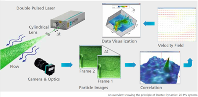
Particle image velocimetry